In PowerVM's virtual networking environment, you know what a Virtual Ethernet adapter is, and why a VM needs Virtual Ethernet adapter mapped against a physical adapter. You know how to bridge the traffic coming out from a VM owning the Virtual Ethernet adapter onto physical network but also recognize the complexity involved in configuring a SEA on a VIOS to achieve this.
It doesn’t end there.
The traffic from the client VM shouldn’t get dropped if the physical adapter backing the SEA fails, or the VIOS itself doesn’t respond. This calls for a fail-over setup. Now, you create another trunk adapter on another VIOS (…and assuming you selected right trunk priority) and create a SEA using this new trunk adapter and a physical adapter on second VIOS. (Oops, did you make sure the physical adapter you are trying to use for creating the SEA is not used by other devices, may be by another SEA or LinkAggregation?)
So far so good!
Did you observe the 10GbE network adapter that you bought and configured SEA with, on the second VIOS, is sitting idle!
Ok, let’s make the best use of both adapters. You configured more trunk adapters on each of the VIOS’s and assigned them to SEAs on each of the VIOSs to balance the load across the SEAs. (Hope you configured/distributed the VLANs properly across the trunk adapters for optimal balancing of traffic across SEAs, and assuming you selected the right trunk priority while adding the new trunk adapters).
Throughout the process, hope you made sure to use the right SEA PVID and the right default virtual adapter to avoid surprises - Good!
Ah, finally!! You did it! The network virtualization works well and bridges the client VM traffic to physical network through SEA(s) configured on VIOS(s).
We were just thinking about the effort you have put in configuring the virtual networking for your VMs and the manual errors you were hitting here and there and the time you spent in identifying and correcting the configuration.
With Enhanced UI, we simplified the virtual network management experience and designed a simple and fresh model that helps you configure networking to the VMs with few simple steps avoiding the chances of user errors (and all that from a single console). With the newer model, configuring network adapter for a VM is as simple as creating a network on the system and adding VM to that network (thats it!).
All that the user has to do is create a Virtual Network on the system, then go to the Partition management and add that partition to the created virtual network (or any other network from the list of configured networks on the system).
To simplify the user experience to such an extent, we needed to work on introducing a completely newer network object model on HMC. (Remember, this is only changing the usage model from HMC to simplify user experience. The effective configuration created on the client partitions, VIOS/SEAs remains the same.)
Before jumping into the configuration walk-through, we will introduce you to the newer network objects, terminology and provide you their relative legacy equivalent object(s):
- Virtual Switch
Same as legacy model, it is the Hypervisor’s implementation of Layer-2 physical switch.
- Virtual Network
Virtual Network is a unique representation of VLAN ID and VSwitch combination within a system.
The virtual networks are classified into below categories:
Bridged and Internal Network
A Virtual Network can be configured either as Bridged or Internal network.
Bridged Network, as the name suggests, allows the traffic from VMs to be bridged onto external physical network through SEA(s) configured on the VIOSs. When selected as Bridged, you need to provide the appropriate VIOS and Adapter details that bridge the traffic from this virtual network to the physical network.
An Internal Network is not bridged. It is used for communication between the VMs within the server.
Tagged and Untagged Network
The Tagged/Untagged property is applicable when the network is bridged.
If the virtual network is untagged, that means the traffic from all the partitions that are connected to this network are routed to the external physical network without the VLAN tagging (Equivalent to PVID of the SEAs).
If the virtual network is tagged, that means the traffic from all the partitions that are connected to this network are routed to the external physical network with the VLAN tag (Equivalent to additional VLAN IDs of the trunk adapters associated with SEA).
- Network Bridge
NetworkBridge is a wrapper object around the existing Shared Ethernet Adapter (SEA) and provides a unique way of managing the network bridge functionality for all configurations like: Failover, LoadBalancing and Non-Failover. When a Virtual Network is created as Bridged, it can either be added to one of the existing bridges' on the managed system or a new Network Bridge is created to bridge the traffic of this network to the external physical network.
Network Bridge can be configured with following options:
Non failover
For Non failover configuration, Network Bridge represents a single SEA. In this mode, a single VIOS and a physical adapter on that VIOS are selected to configure a SEA.
Failover enabled
A Failover Network Bridge represents a pair of SEAs configured on two VIOSs. With Failover, HMC provides the option to choose two VIOSs and a network adapter each on those two VIOSs. In failover configuration, the primary SEA will bridge the traffic from virtual to physical network. In case the primary SEA (or VIOS) fails, the traffic is bridged through the secondary SEA.
Load Sharing Enabled
HMC provides an option to enable Load Sharing on the NetworkBridge. By enabling Load Sharing, the network traffic from a subset of virtual networks is shared among the SEAs within the Bridge.
With Enhanced UI, user only needs to select whether they want a failover or non-failover bridge for the network. HMC will create equivalent SEA configurations on the selected VIOSs and hide the complexity of the configuration from user.
- Load Group
To further simplify the load sharing configuration of VLANs bridged by SEA pair, the new Network Model introduced the concept of LoadGroup within the Network Bridge. Load Group is a pair of Trunk Adapters with the same VLAN and Vswitch configuration created on two VIOSs within the SEA pair. Two trunk adapters with overlapping VLAN IDs and different trunk priorities makes a pair within the bridged setup. This pair is represented as single LoadGroup in the new user model.
A user creating a new virtual network on the managed system has the option to either create new NetworkBridge for that network or add the network to an existing NetworkBridge. While adding the network to an existing NetworkBridge, the user can choose the LoadGroup to which the network needs to be added. In Load Sharing scenario, the virtual networks are shared among the SEAs at Load Group level. Set of Networks associated with a LoadGroup (a trunk adapter pair) are bridged by one SEA and set of networks associated with another LoadGroup are bridged by second SEA within the NetworkBridge.
The table below summarizes the relationships of the newer objects with existing legacy model:
| Enhanced UI Model |
Equivalent Legacy Model |
| Virtual Switch |
Virtual Switch |
| Virtual Network (New) |
- |
| Network Bridge |
Single SEA (non-failover) OR
Pair of SEAs (failover/load balancing) |
| Load Group |
Trunk Adapter on SEA (non failover)
OR
Pair of Trunk Adapters with exact same configuration across two failover/load balancing SEAs |
Virtual Network Management through Enhanced GUI
This section provides the overview of Bridged Virtual Network configuration on the managed system with the simplified UI.
- View Virtual Networks in the system
The screen below shows the list of virtual networks and associated Network Bridges in the system. In the example screen below, we have one virtual network (not Bridged). The highlighted button (green box) provides the option to add a new virtual network in the system.
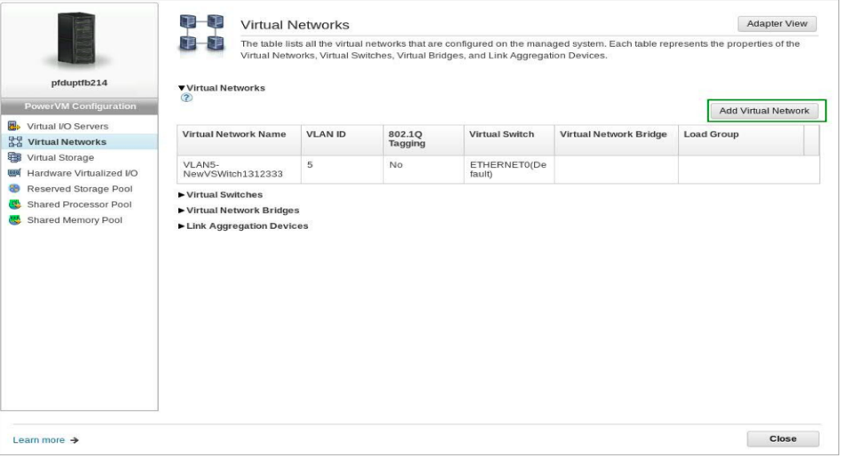
Figure 1. System level virtual networks view
- Create a Bridged Virtual Network
When “Add Virtual Network” is selected from the above page, you will be asked to provide some of the minimal network details as shown in screen below.
As highlighted below, you have the option to select the Network type: Bridged or Internal, Tagged or Untagged, and select the VSwitch and VLAN ID with which the Network needs to be configured.
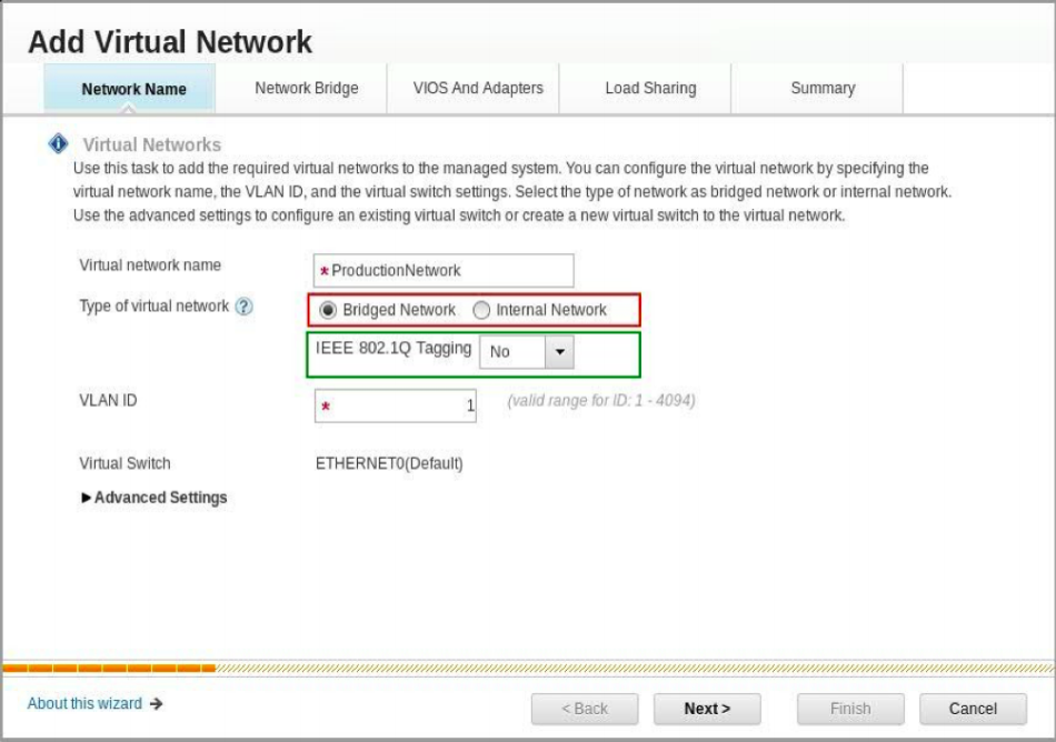
Figure 2. Add virtual network - virtual network parameters
While creating the Untagged Virtual Network, the VLAN ID of the Virtual Network is used as the PVID of the Network Bridge (which is the PVID of SEA). In the case of Tagged Virtual Network, you need to specify the PVID of the Bridge (which is used as PVID of SEA). In this case, the VLAN ID of the Tagged Virtual Network is configured as an additional VLAN ID on the SEAs Trunk Adapter. When Selected as Bridged Network, appropriate Bridge details will be provided in the next step. If user opted for an Internal Network, no Network Bridge details need to be provided. With Advanced setting shown in the above figure, you can select a different VSwitch (than the auto selected Default Switch or create a new VSwitch)
- Network Bridge details
Once the Virtual Network Type, VLAN ID and VSwitch are selected in above screen, you will be prompted for the NetworkBridge properties.
In this step the user has the option to select the Network Bridge configuration. It provides the option to choose whether the Failover, Load Sharing, etc. is required. It also provides certain interface specific attributes to be configured on the created SEA like: QoS, Jumbo Frames, etc.
In case that Load Sharing is enabled, you need to provide the second LoadGroup details, as highlighted in Green below. The first Load Group is created with the NetworkBridge PVID. The chosen Virtual Network will then be added to the default LoadGroup while creating the NetworkBridge.
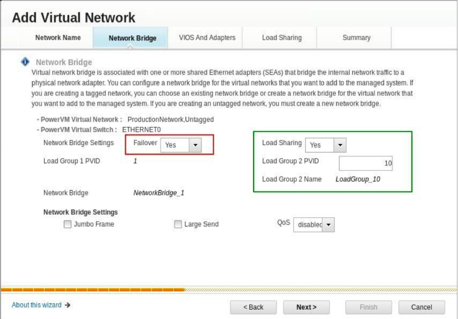
Figure 3. Add virtual network - network bridge parameters
- VIOS and Backing Ethernet Adapter details
Based on the configuration selected in the previous page (either failover enabled or not), this page provides the user an option to choose either single or dual VIOSs along with the Physical Network device on each. As highlighted below, HMC also provides an option to configure the Network interfaces of the created SEAs with the provided IP details. In this page, HMC will list only those physical adapters which are available for creating the SEA. This will avoid user verifying the usage of each of those adapters by any other SEA or LinkAggregation devices.
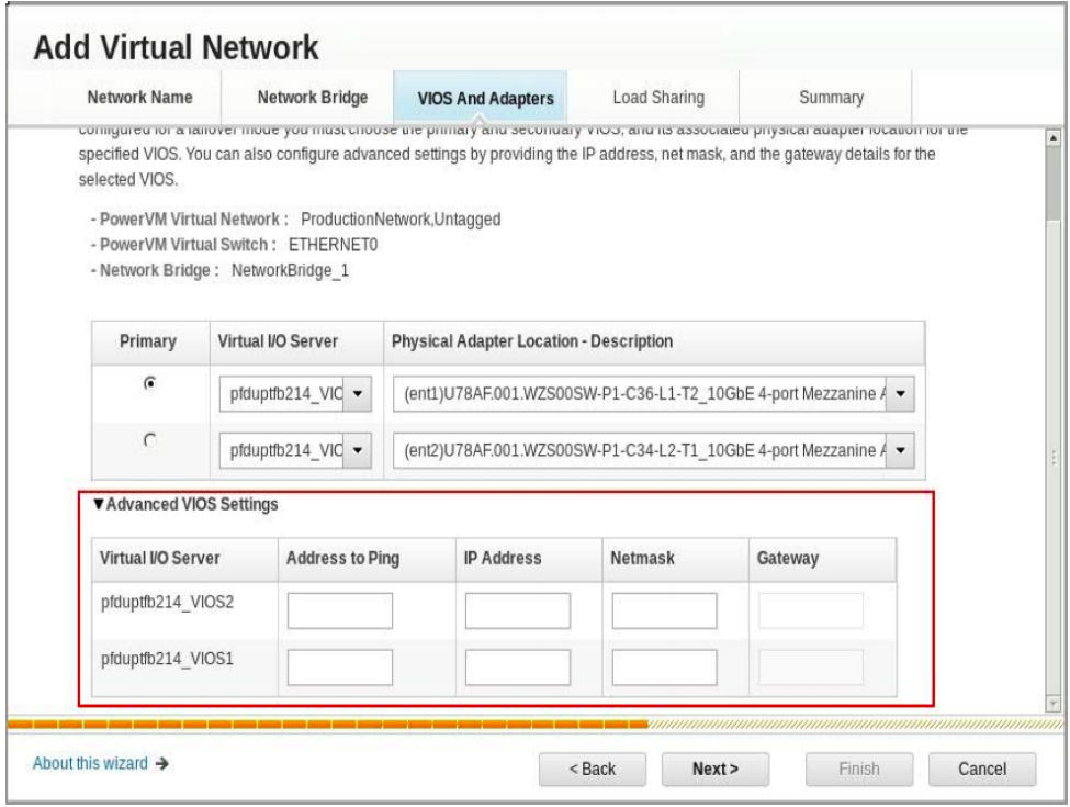
Figure 4. Add virtual network - vios and physical adapter selection
- Configuration Summary
The final page of the wizard shows the summary of the configuration selected by the user.
You can switch the view between Adapter and Virtual Network view (via the button highlighted below) to configure the virtual adapter details for the VIOS. HMC uses default attributes for the virtual ethernet adapters that will be created as a result of this configuration deployment. You can use the adapter view to work with the finer or granular details like adapter slot number, etc.
Clicking on Finish will configure the Virtual Network setup on the Hypervisor and both VIOSs. The configuration result in the following actions:
- Creates a Virtual Network on the system
- Creates Trunk Adapter(s) on each of the VIOSs (either one or two based on the load sharing selection)
- Creates the Shared Ethernet Adapter(s) on each of the VIOSs with the selected Physical Adapter as the backing device.
- Configures the created SEAs with the IP details provided.
All this is achieved from HMC console and the user doesn't need to switch between HMC and VIOS consoles.
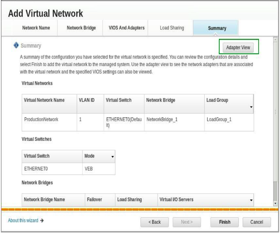
Figure 5. Add virtual network - configuration summary
The screen below shows the resultant Virtual Networks view with newly created Virtual Network and Network bridge. The Virtual Networks table shows the newly created Virtual Network (highlighted in green) along with the associated Network Bridge and LoadGroup. The Network Bridges table shows the created Network Bridge (highlighted in green) and the associated VIOSs it is configured on.
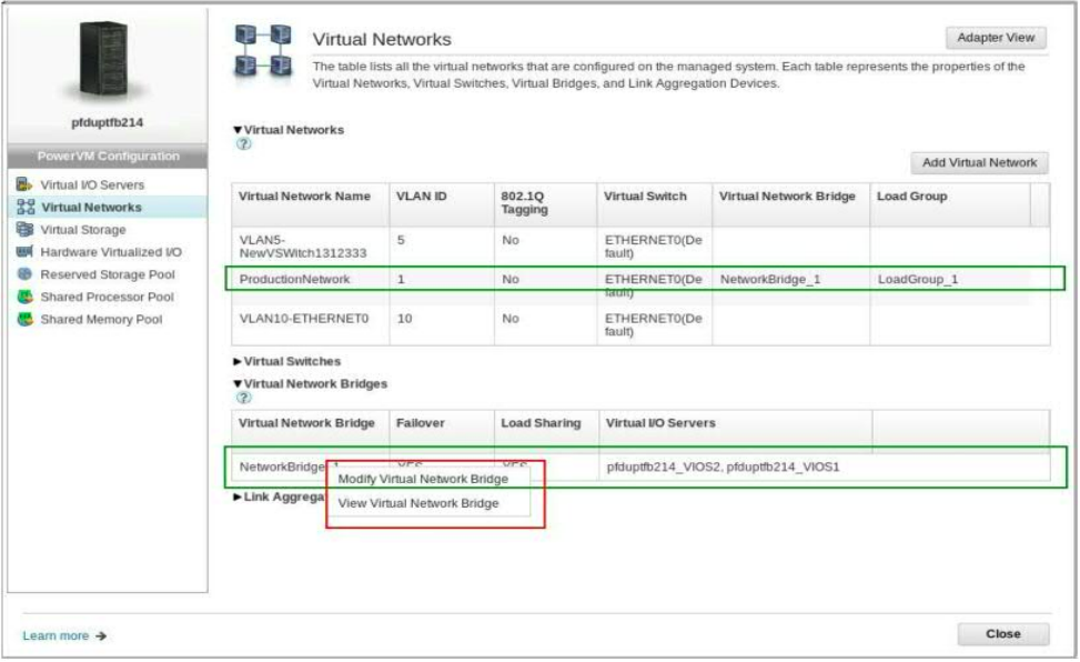
Figure 6. Virtual Networks view after the new network addition
- Modify NetworkBridge
You can modify the Network Bridge properties by right clicking on the Network Bridge as highlighted in Red in above Figure 6.
The modify Network Bridge panel provides the option to change the backing physical network adapter and set some of the SEA specific attributes like QoS etc. as highlighted in Figure 7.
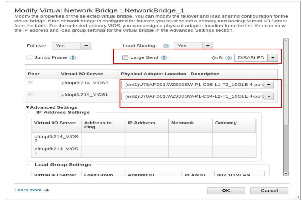
Figure 7. Modify network bridge properties
While the above Virtual Network creation flow is referring to creating a new Network Bridge, you can choose to add the Virtual Network to one of the existing Bridges.
The section below covers the procedure for creating and adding the virtual network to an existing Network Bridge.
Create a Bridged Network with Existing Network Bridge
While creating a new virtual network, if a Network Bridge already exists in the system, you will have option to either add network to one of the existing bridges or create a new bridge. We can create a Virtual Network with existing bridges only if we are creating a tagged network with existing virtual switches. To create a virtual network with one of the existing bridges, we create a Tagged Network with existing virtual switch and provide VLAN ID for the network, and click on Next to select bridge from the existing bridges.
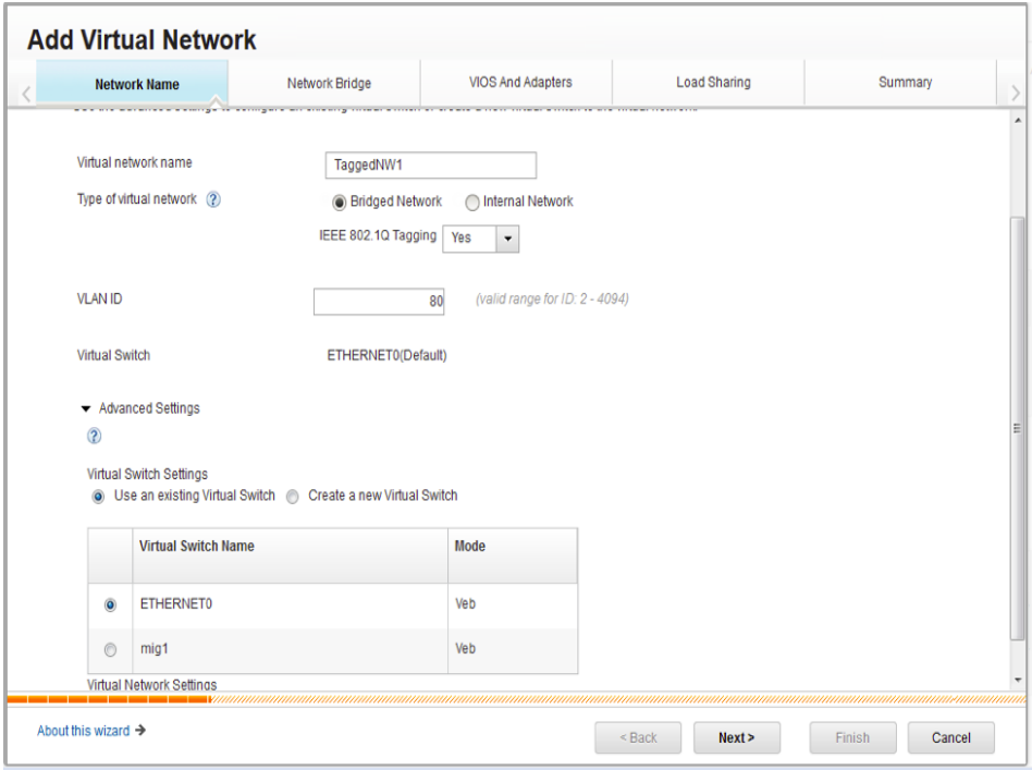
Figure 8. Add virtual network with existing bridge
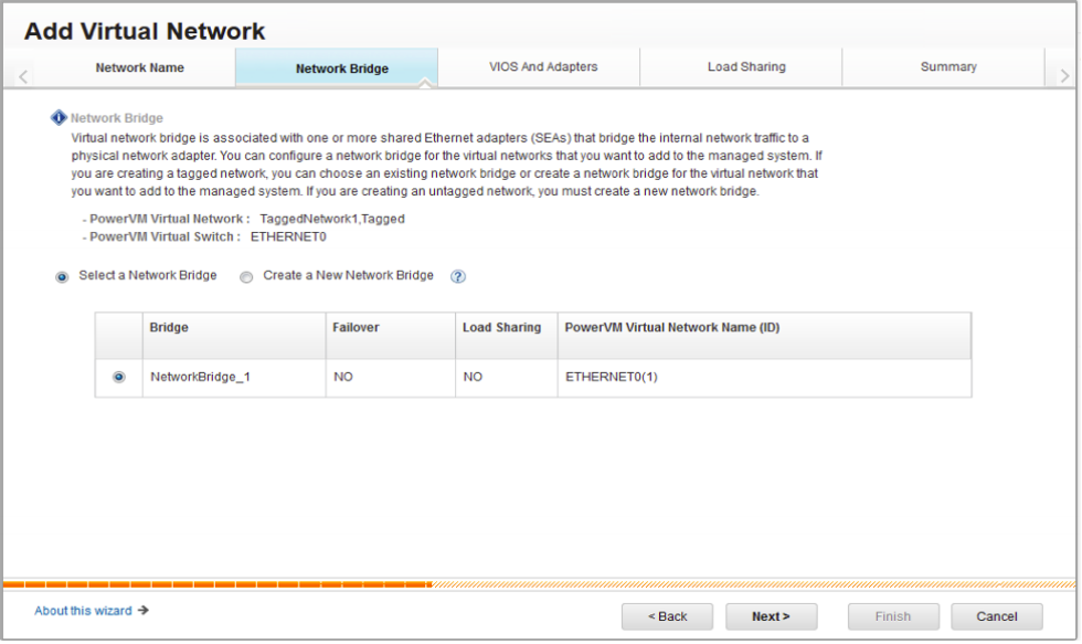
Figure 9. Add virtual network - select the bridge
After selecting the Network Bridge and clicking on Next, you will be taken to the Load Sharing option. (Since the Network Bridge is already existing, you will not be prompted to select the VIOS and Adapters for creating SEAs)
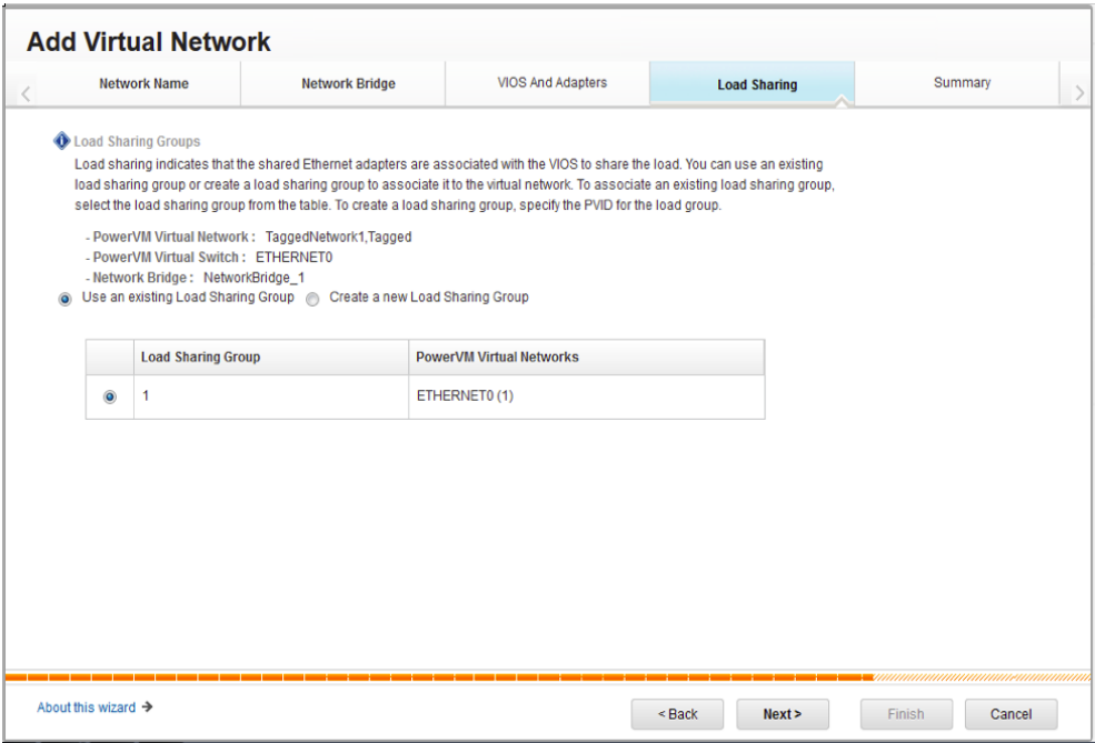
Figure 10. Add virtual network - select the load group
As shown in above screen, you have the option to either select one of the existing Load Groups (a Trunk adapter pair in legacy terms) to which the newly created network will be added, or you can choose to create a new LoadGroup by providing a PVID. In the later case, a trunk adapter pair gets created on both SEAs with specified PVID and the network is added as additional an VLAN ID into these trunk adapters. The complexity involved in creating trunk adapters, updating the same with additional VLAN IDs and associating the new trunk adapters with SEAs is all handled by the HMC in the background. All you need to do is select the LoadGroup to which the network needs to be added.
Click 'Next' to summarize the configuration and then click ‘Finish’ to add virtual network to the NetworkBridge.
Manage Network Connections of the Client Partition
Having a Bridged Virtual Network configured on the Managed System, you can now add a Client Partition to this Virtual Network in simple steps through “Manage Partition”.
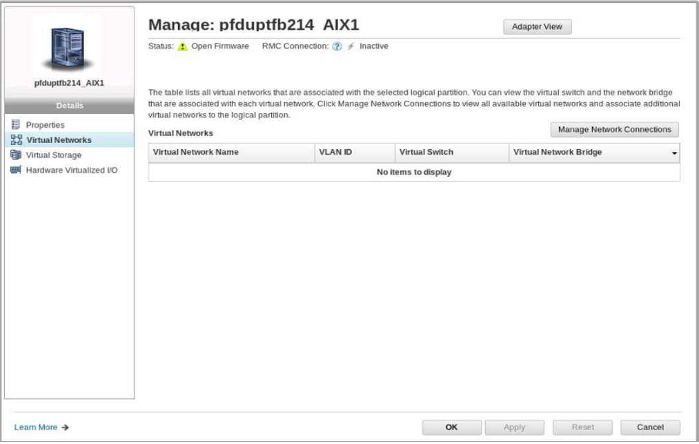
Figure 11. Virtual network view of client partition
Clicking on “Manage Network Connections” shown in Figure 11 lists all the virtual networks configured on the managed system and provides option for selecting the networks to which the partition needs to be added (as shown in Figure 12). Please note that the "Manage Network Connections" option is not enabled when there is no active RMC connection on a Running partition.
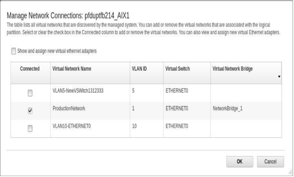
Figure 12. Virtual network selection for client partition
Select the appropriate Networks to which the Partition needs to be connected and click on 'OK'. This will create a Client Network Adapter on the Partition with configurations equivalent of the virtual network selected (Network's VLAN ID and VSwitch as the VEth adapter's PVID and VSwitch respectively).
In summary, we have made it simple to work with virtual networks by abstracting some of the finer details and are very interested in hearing your feedback on this simplified model.