Suppose you have a new z16 and you or someone on your team has just completed CHPID Mapping using the CHPID Mapping Tool. You may be pondering how can you visually describe the CHPID locations to the team in your organization responsible for cabling? What about when there are component failures? How can the datacenter team trace back to the physical source and endpoints relevant to that failure? This is where a diagram can come in handy describing what frame, drawer, slot, and port your end points connect to. The purpose of this two-part series is to show you a way to provide a clear interpretation of the z16 I/O infrastructure and within it - what devices are connected to each CHPID or port. To use this approach for documenting IO connectivity you will need:
· A basic understanding of the machine model/layout. In other words which model, how many frames and how many CPC and I/O drawers make up the machine. In this document we are using a z16 with device type 3931-A01 comprised of 2 frames, 2 CPC drawers and 4 I/O drawers (see Appendix A).
· IBM CHPID Mapping Tool
o Inputs needed – the “CFR file” provided by IBM after the machine is ordered and the IOCP the systems programmer has created to represent the new or old machine (old machine is applicable when migrating from an older machine). In the CHPID mapping process, CHPIDs are assigned from the IOCP input file and mapped to the Physical Channel Path Ids (PCHIDs) of the new machine. Using the CHPID mapping tool helps with these assignments. When the resulting IOCDS is loaded during activation of the CPC hardware, the CHPID to PCHID assignments become part of the configuration. In documenting connectivity, we will use the following outputs from the CHPID Mapping Tool. When complete, these outputs provide a detailed list of all I/O features and the devices each I/O port connect to.
§ CHPID.rpt
§ Control Unit.rpt
§ CHPID to CU.rpt
Note: The CHPID Mapping Tool is a topic in-of itself which is not covered in this document. IBM does provide a CHPID Mapping Tool User’s Guide (GC28-7024-01) that is available for download, for example from CHPID Mapping Tool User's Guide - IBM Documentation
· Microsoft Visio will be used to create and store the diagrams in Visio format. Completed diagrams can also be saved in another format such as JPEG or PDF if desired.
Resource Link
First a bit about IBM ResourceLink. Resource Link has several tools available for IBMz customers, in fact this is likely where the CHPID Mapping tool was downloaded by the person responsible for creating the I/O definitions for the new machine. The benefit of Resource Link is that once you have a user ID that’s associated with your organization’s IBM account(s), several tools are made available for your specific IBMz machines. These tools are a great help in planning for implementation, finding education, obtaining the latest hardware documentation, viewing the current hardware maintenance/support levels and capacity on demand information. What you may not know is there are tools a customer can use for planning and diagramming connectivity for your z16.
To use Resource Link, you first need an IBMid. Once you have an IBMid you may need help from your IBM account team to associate your IBMid to your organization. The link to Resource Link is below which includes information for new users.
https://www-40.ibm.com/servers/resourcelink/svc03100.nsf?Opendatabase

Figure1 – IBM Resource Link main page
Once you are in Resource Link, you should see a screen like the one below. Under the IBM Z section, Resource Link displays the different IBMz generations/models. Next click on the machine you are interested in, for example an IBM z16-A01.

Figure2 – After logging in with valid Resource Link ID
There will be several links on the next page. For our purposes I’ve highlighted the download selection “Product drawings: Visio files”. Choose this to download Microsoft Visio stencils for the z16.

Figure3 – Available resources for IBM z16-A01
Once you have downloaded the Visio stencils for this model, open the file and you will be presented with a set of Visio objects (see Appendix B).
Stay tuned for Part II where I will demonstrate how to use the reports from CHPID Mapping to create a Custom image of your machine and the physical connectivity.
~~~~~~~~~~~~~~~~~~~~~~~~~~~~~~~~~~~~~~~~~~~~~~~~~~~~~~~~~~~~
Appendix A – Sample z16:
The image below represents a 3931-A01 which contains:
· 2 frames (A and Z frame)
· 2 CPC drawers within the A-frame (A10B and A15B)
· 4 I/O drawers (A31B in A frame and Z01B, Z09B and Z17B in the Z frame). Each I/O drawer contains 16 card slots numbered 02-05, 07-10, 12-15, and 17-20.
Each slot within an I/O drawer will contain a card for whatever I/O feature is assigned to it by The CHPID Mapping Tool or a filler/blank card. Note that each slot has 2 PCHPIDs assigned, for example in drawer A31B, slot 02 is assigned PCHPID 100 and 101. As you can see the PCHPIDS are numbered from the center of each slot. Slots on the left side of the I/O drawer have PCHPIDS going from center to the left and slots on the right have PCHPIDS going from center to the right.
PCHPID assignments for a given slot are set at the plant and cannot be changed. Later, through the CHPID Mapping process, the 2-character logical CHPIDs will be assigned.

~~~~~~~~~~~~~~~~~~~~~~~~~~~~~~~~~~~~~~~~~~~~~~~~~~~~~~~~~~~~
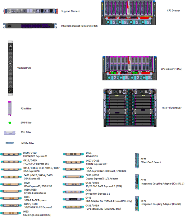
Appendix B - Visio stencils included in the download from Resource Link
IBM Provides several blank stencils for various I/O cards and for the CPC and I/O drawers. The horizontal mages on the lower section represent various I/O adapters that can be plugged in to various slots on the CPC and I/O drawers. Note that some of the feature codes below may not perfectly match to your machine. For diagramming purposes that's no sweat as long as you represent the cards you plug into the slot with a similar sample of the same card type and number of ports. For example, if your machine has an OSA Express 7s 10Gbe SR but there is no image for one, you can substitute the OSA Express 7s 25Gbe SR image and label it appropriately in your diagram - more on that in Part II.
The main idea here is that these stencils combined with the CHPID Mapping tool create the canvas for creating your representation your physical I/O connectivity.

~~~~~~~~~~~~~~~~~~~~~~~~~~~~~~~~~~~~~~~~~~~~~~~~~~~~~~~~~~~~
Stay tuned for Part II where I will provide a continuation on how to complete the process in documenting I/O device connectivity.
